MIL-DTL-24050E
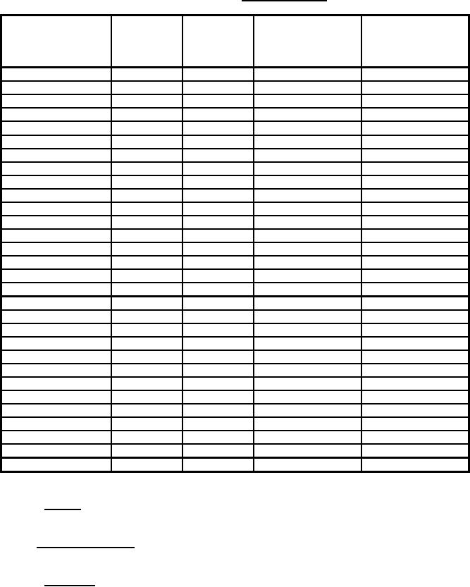
TABLE III.
Physical Properties.
Circumference
Diameter
Linear density
at load P
(nominal
Load P
plus or minus
Breaking strength
(nominal inches)
inches)
(pounds)
5 percent
(minimum pounds)
(pounds/100 feet)
3/4
1/4
13
1.52
1785
1
5/16
20
2.38
2835
1 - 1/8
3/8
28
3.42
4095
1 - 5/16
7/16
38
4.65
5355
1 - 1/2
1/2
50
6.06
7245
1 - 3/4
9/16
63
8.26
9450
2
5/8
78
10.8
12600
2 - 1/4
3/4
113
13.9
15750
2 - 1/2
13/16
132
16.7
19320
2 - 3/4
7/8
153
20.4
23625
3
1
200
24.3
27825
3 - 1/2
1 - 1/8
253
33.1
37800
3 - 3/4
1 - 1/4
313
38.0
44100
4
1 - 5/16
345
43.3
50400
4 - 1/2
1 - 1/2
450
54.6
64200
5
1 - 5/8
528
67.6
78110
5 - 1/2
1 - 3/4
613
82.0
96300
6
2
800
97.1
109675
6 - 1/2
2 - 1/8
903
114.0
131610
7
2 - 1/4
1013
132.0
149800
7 - 1/2
2 - 1/2
1250
152.0
171200
8
2 - 5/8
1378
173.0
192600
9
3
1800
219.0
243000
10
3 - 1/4
2113
270.0
284840
11
3 - 1/2
2450
327.0
351000
12
4
3200
389.0
415800
13
4 - 1/4
3613
450.0
475200
14
4 - 1/2
4050
524.0
548640
15
5
5000
600.0
622080
16
5 - 1/4
5513
685.0
702000
3.4.3 Texture. The texture of the finished rope shall be firm without sleaziness, and the cover (outer braid)
shall fit closely around the core (inner braid) when inspected with the rope in a relaxed state.
3.5 Physical requirements. The finished rope shall conform to the physical properties specified in table III
when tested as specified in 4.5. The circumference in accordance with table III shall be as specified (see 6.2).
3.5.1 Elongation. The elongation of the ropes shall not exceed 40 percent at the minimum breaking strength
when determined as specified in 4.5.5. The load elongation curve, drawn autographically, shall not exhibit
evidence of sudden changes in load applications greater than 5 percent of the load weighted at the instant of
change. Changes due to splice slippage shall not be considered in this determination.
4
For Parts Inquires call Parts Hangar, Inc (727) 493-0744
© Copyright 2015 Integrated Publishing, Inc.
A Service Disabled Veteran Owned Small Business